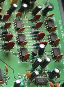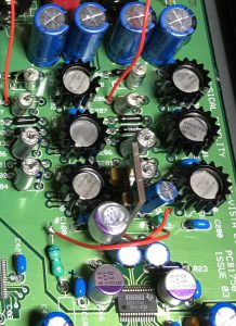
Now we get to to the heart of the project – the DAC section.
MF made some mistakes in the analog power supply and the op amp filters. Below I will show you how to correct these mistakes and unlock tremendous improvements. Trivista uses a Burr Brown DSD1792A 24/192 DAC in PCM mode. This chip was state of the art in 2003 and boasts 127dB dynamic range and 0.0004% (-108dB) THD+N, which is comfortably beyond the performance required for CD audio. DAC chips are all quite cheap (tens of USD) on their own but they need good supporting circuits to make them sound good. TI published a reference circuit in the 1792 data sheet and I will refer to parts of it as we proceed.
+5V DAC chip analog power supply. DAC chips need separate clean +5V for the analog power pins. So why did MF supply the DAC chip’s analog power pins VCC2L and VCC2R from the dirty digital 5V power rail? After analysis confirmed by listening tests I concluded this was indeed a mistake probably made when they designed the PCB. There actually is a clean +5V rail supplied by a 7805 regulator with choke filtering that takes power from the already clean +15V analog rail but it is only used for the DAC chip’s VCC1. Get out your soldering iron and connect the DAC chip’s VCC2L and VCC2R pins to the clean analog +5V rail. You have just doubled your Trivista 21’s sound quality. For further improvement replace the 7805 regulator with something better. In this critical application the difference between a fairly good LM340A and a state of the art (in 2017) LT3045 is clearly audible in terms of transparency, resolution and spaciousness. If you want perfection you can use 3 LT3045 to power VCC1, VCC2L and VCC2R but you would need to make a piggy back board. Finish off with a sprinkling of OSCON on the DAC chip power rails. Don’t use OSCON for the internal bias decoupling caps because they have high leakage current. You have now doubled the sound quality again.
+15 and -15V op amp power supply. Each rail is provided by one 78/79 regulator taking power from the +-24 volt rails. Each regulator supplies both left and right channels. Putting in separate regulators for the left and right op amps would have cost USD5 more in components so this kind of cost cutting by MF is surprising. Unfortunately, there’s not much that can be done without seriously cutting up the PCB so I have left as is and merely upgraded the regulators to LM340. At least there is room to put in decent electrolytics.
Op amp integrator and filter. MF uses the reference circuit and I agree 100%. Some hobbyists claim they can come up with a better circuit, if they are so good they can go and design the DAC chip as well. However here is where MF made another mistake on the PCB (but not on the circuit). For some reason MF uses half of a 5532 dual op amp in all six positions instead of the recommended single 5534. That in itself is not a problem and maybe they had a lot of 5532 in stock. But they failed to disable the unused half of the 5532’s in the correct way. They wired both inverting and non-inverting inputs to ground, which ensures the output is driven at open loop gain and will peg itself at the + or the – power rail at random. Thus the non-working half of each 5532 compromises the working half. Correction requires track cutting to reconnect the inverting input to the output to regain stability. While you are working on the op amps why not use something better? The data sheet specifies the 5534 loved by big Japanese electronics companies who are the main customers. But the same circuit appears in OPA1611/12 data sheet so TI engineers know better. I am using LME49710 and LME49720 but if you use AD797 I would love to hear from you. While you are in there replace those cheap resistors and capacitors in the filters with your favorite precision types. I went with 0.1% Dale metal films with 5 and 15 ppm/C and hand matched 1% Phillips NOS polystyrene. There’s not much space to put in anything bigger/better.
Output buffer added. The output of the third op amp is ready to feed into your preamp. In the Trivista 21 this signal is connected to the input of the tube stage and is not available at the back panel. I added an LME49720 unity gain buffer stage so I could bring this clean signal to some extra phono sockets on the back panel to facilitate A/B comparison with/without the tube stage.
Figure 5: DAC original Figure 6: re-engineered